Plating Lines & Equipment
Rectifier Buying Guide Electroplating
The rectifier is the heart of any electroplating line — it delivers the DC current that drives the deposition process, and its quality directly determines deposit uniformity, current efficiency and su
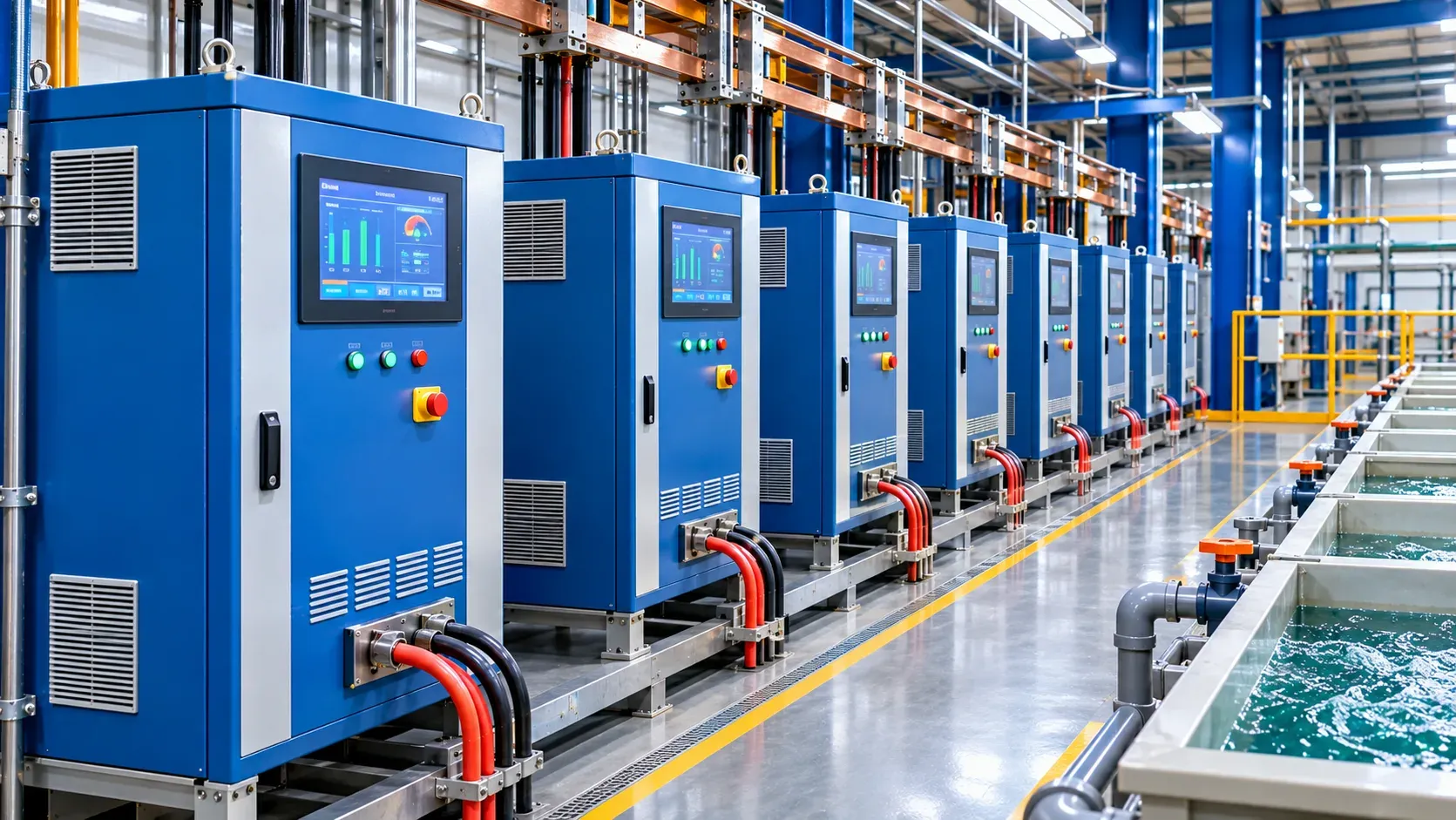
The rectifier is the heart of any electroplating line — it delivers the DC current that drives the deposition process, and its quality directly determines deposit uniformity, current efficiency and surface finish. Buying the wrong rectifier means buying coating defects that no chemistry change can fix. This guide covers what to specify and what to verify.
Technical planning document — confirm ratings against your loaded area calculation and chemistry supplier's recommended current density.
The specification parameters
Parameter | What to specify | Why it matters |
|---|---|---|
Output current (A) | Peak current for the maximum loaded area × the chemistry's recommended current density | Undersized rectifiers cannot deliver the current density the chemistry needs |
Output voltage (V) | Enough to overcome solution resistance plus busbar losses — typically 6–12 V for most plating | Undervoltage limits current delivery; overvoltage wastes energy |
Ripple | Less than 5% ripple for most plating; some chemistries specify lower | High ripple causes deposit roughness, burning and uneven thickness |
Regulation | Constant voltage (CV) or constant current (CC) mode — most plating uses CV | CV mode maintains voltage as the load changes; CC mode maintains current |
Control resolution | Digital control with 0.1 V / 0.1 A resolution and programmable steps | Fine control is needed for current-sensitive chemistries and step plating |
Cooling | Air-cooled for most installations; water-cooled for high-power or enclosed spaces | Air-cooled rectifiers need ventilation; water-cooled need a water circuit |
Remote control | 0–10 V or 4–20 mA analogue input, or digital (Modbus/PROFIBUS) for automated lines | Automated hoist systems need programmable rectifier control |
Sizing the rectifier
The output current is calculated from the maximum loaded area and the chemistry's recommended current density:
Output current (A) = Total loaded surface area (dm²) × Current density (A/dm²)
Example: a rack holding 40 parts, each with 2 dm² of surface area, plated at 4 A/dm² — total loaded area = 80 dm², required current = 320 A. A 500 A rectifier gives 25% headroom for larger loads or higher current density steps.
The output voltage must overcome the solution resistance between anode and cathode, plus the contact resistance at racks and busbars. Most plating solutions operate at 3–6 V of solution voltage; add 2–3 V for busbar and contact losses. A 12 V rectifier covers most conventional plating; 18 V or higher for high-resistance electrolytes or long busbar runs.
Rectifier types
Type | Ripple | Efficiency | Best for |
|---|---|---|---|
Switching mode (SMPS) | Very low (< 1%) | 85–92% | Modern production lines — compact, efficient, precise control |
Thyristor-controlled (SCR) | Low (2–5% with filtering) | 80–88% | Higher power applications, robust production environment |
Transformer-tap | High (unfiltered) | 70–80% | Legacy equipment — not recommended for new installations |
Switching-mode rectifiers are the modern standard: lower ripple, better efficiency, smaller footprint and digital control built in. Thyristor-controlled units are still used for very high power applications (over 5000 A) where switching-mode rectifiers are less cost-effective.
Key takeaways
- Size the output current from the maximum loaded area × the chemistry's recommended current density.
- Ripple below 5% is essential for smooth deposits — switching-mode rectifiers provide this natively.
- Constant voltage (CV) mode is the standard control for most plating chemistries.
- Remote control (analogue or digital) is needed for automated hoist systems and step plating.
- Switching-mode rectifiers are the modern default: efficient, compact and precise.
Your next five steps
- Calculate the maximum loaded surface area per tank from your part range and racking.
- Multiply by the chemistry's recommended current density to get the output current.
- Add 25% headroom for larger loads and process flexibility.
- Specify switching-mode with CV mode, remote control and ripple below 5%.
- Confirm the voltage rating covers the solution resistance plus busbar losses.
FAQ
What is ripple and why does it matter?
Ripple is the AC component that remains after rectification. High ripple causes uneven current distribution, deposit roughness and reduced current efficiency. Modern switching-mode rectifiers have ripple below 1%.
Should we use constant voltage or constant current mode?
Most plating chemistries use constant voltage (CV) mode — the voltage is maintained and the current adjusts to the load. Constant current (CC) mode is used for specific chemistries and processes where current density must be held exactly.
What size rectifier for a barrel plating line?
Barrel plating needs higher current than rack plating because the current spreads across all the parts in the barrel. Calculate the total surface area of all parts in a barrel load and multiply by the current density — the result is typically 200–600 A per barrel.
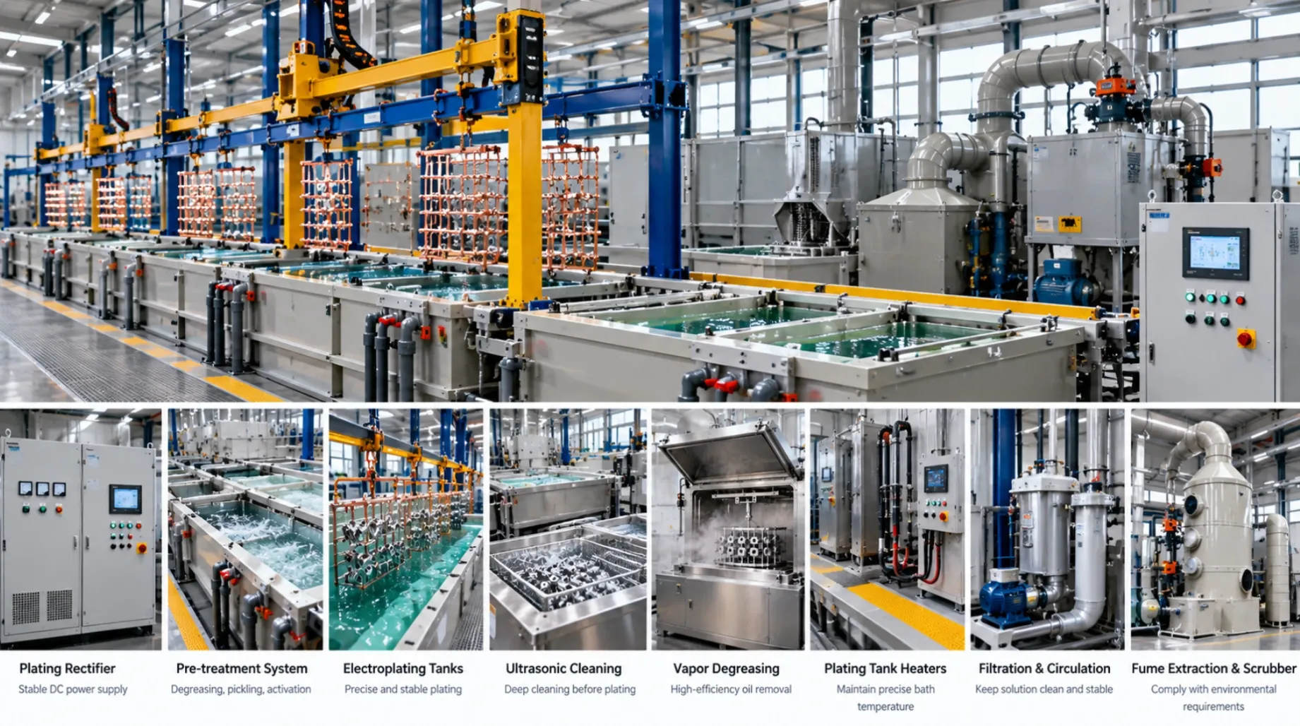
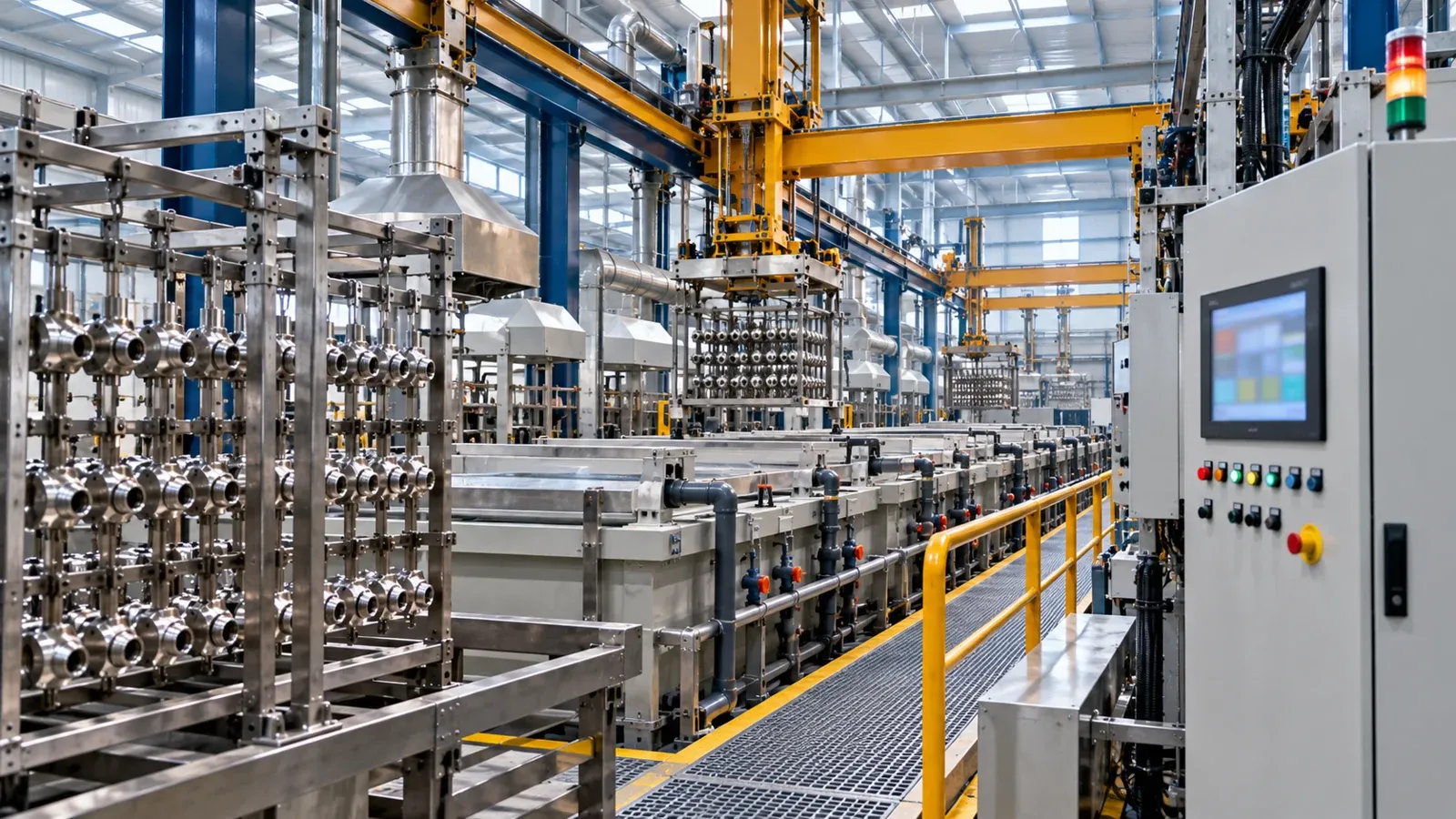
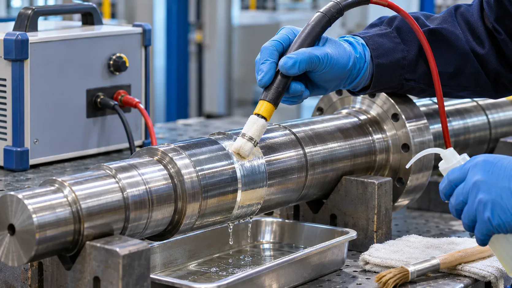
Image note: AI-generated editorial photography illustrates equipment or workpiece contexts; it is not an ES-PRO installation, customer reference or evidence of coating performance.