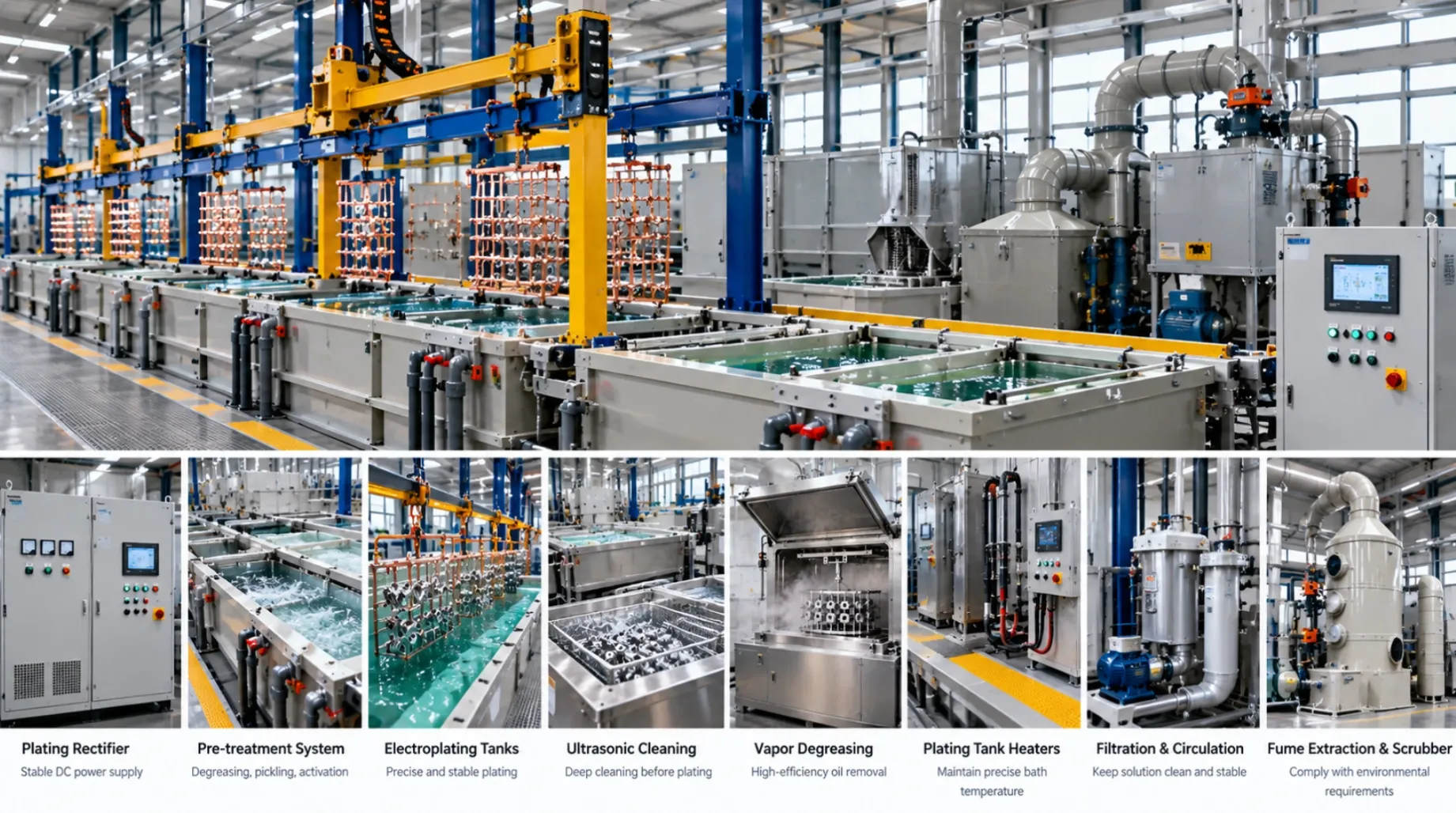
Plating Lines & Equipment
Surface Area Records for Plating Rectifier Loads
Prepare a surface area basis for a plating rectifier load. Record coated faces, masking and occupancy, then check the assumptions with a worked example.
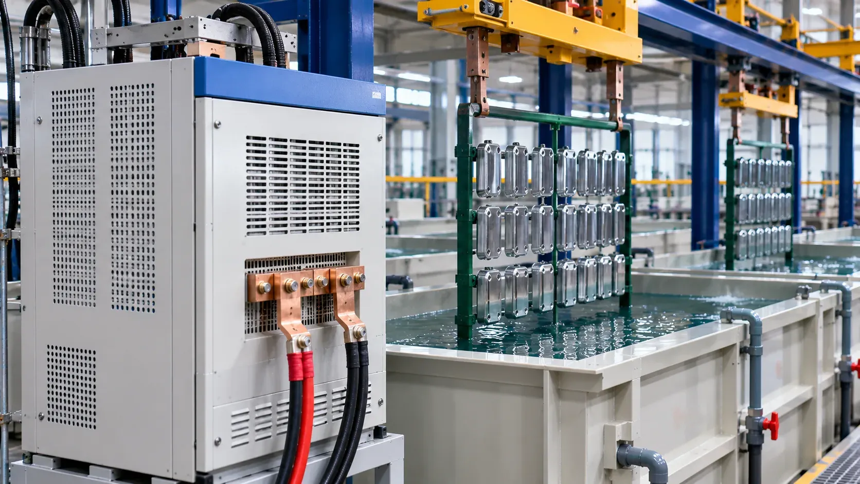
Prepare a rectifier load from the surface area that will be plated, the number of parts and the process owner's approved current-density basis. Record coated and excluded surfaces explicitly. Keep the calculation linked to the qualified rack or barrel load, then verify the electrical duty and actual thickness evidence for that configuration.
A part's outside dimensions do not describe every coated surface. Holes, recesses and internal surfaces can matter, while a masked area may be excluded. The estimate needs enough detail that the process engineer and equipment supplier can check the same boundary.
Define which surfaces belong in the estimate
Start with the part drawing and finish callout. Mark required coating, excluded surfaces and contact zones. Record the method used to obtain the area, such as a documented CAD selection or a checked geometric estimate. Keep a record of features that remain uncertain and how the owner will resolve them.
Distinguish part area from any additional electrically active area considered in the approved load. Ask the process owner how rack exposure or other conductive items enter the electrical basis. A fixture's apparent envelope alone does not give the electrically active area.
Area input | What to document | Check before sizing |
|---|---|---|
Required coated surfaces | Drawing zones and area calculation | Did the estimate include the correct faces and features? |
Exclusions | Masking and contact zones | Are those exclusions present on the actual load? |
Load quantity | Approved occupied positions or barrel load | Does the electrical basis match production occupancy? |
Process current basis | Approved current density and stage | Does it apply to this coating route and load? |
The Nickel Institute handbook explains the relationship between current, area and deposition in nickel plating. Use the process owner's actual values for the project. Local distribution still needs its own measurement evidence.
Work through an area calculation
Consider a hypothetical rack carrying 20 parts. Each part has 0.18 square metres of coated area after the agreed exclusions. The total part area is 3.6 square metres, or 360 square decimetres. At an illustrative process basis of 2 amperes per square decimetre, the calculated part current is 720 amperes.
These numbers demonstrate units and arithmetic. The approved process determines the usable current density. If a later drawing change increases coated area to 0.21 square metres per part, the same 20-part load becomes 420 square decimetres and 840 amperes at that illustrative basis. A small change to one part can materially change the load total.
Keep the calculation readable. Write the area per part, unit conversion, occupied count and process basis as separate inputs. If the total includes other active area or a specified margin, show those separately with their owner. A supplier can then distinguish an actual duty requirement from an unverified estimate.
Check both ends of the production range
Ask how the proposed rectifier performs on the smallest and largest approved loads. A machine selected for the full rack still needs a usable operating range and controls for a smaller run. Record whether the line changes the electrical program when occupancy changes and how the selected program is tied to the load.
Use the rectifier selection guide to specify output quality, cooling, controls and measurement conditions. For barrel work, connect the calculation to the barrel load factor guide. The current estimate is one input to selection alongside voltage and circuit conditions.
Confirm the result on the part
Agree the thickness map and measurement method before the trial. A calculated average duty does not establish that a recessed surface meets a local requirement. Compare the electrical record with part measurements at the defined locations. Keep the load layout, area revision and current program together.
Record drawing revision · coated area method · exclusions · area per part and units · loaded count · other active area · approved current basis · calculated current · actual program · thickness evidence. The coating thickness testing guide helps organize the measurement plan.
Ask a second reviewer to reconstruct the example from the marked drawing and area record. Resolve any face that one reviewer included and another excluded. Keep the accepted selection or sketch with the calculation so an engineer receiving a revised CAD model can see what to update.
FAQ
Can I multiply length by width to obtain plating area?
Use a method that includes the coated surfaces and relevant features. A projected area may omit the reverse face, edges and recesses.
Does the largest possible rack define the rectifier duty?
Use the approved load range and process programs. Confirm the intended electrical duty at both low and high occupancy.
Can I choose current density from this example?
Obtain the approved process basis from the process owner. The example shows the calculation structure.
Discuss an electrical load basis
Share your part drawing and occupied load. Include the area calculation, exclusions and approved current basis. Send records by sales email, or discuss the project on WhatsApp.