Plating Racks: Design Inputs, Contact Marks and Upkeep
Define plating rack requirements using part orientation, contact marks, loading, drainage and maintenance. Prepare a tooling brief for your plating line.
Plating racks should be assessed against part orientation, electrical contact, acceptable marks, loaded weight and drainage. Begin with a marked part drawing and representative loading requirements. Rack capacity expressed only as a part count leaves important quality and handling questions unanswered, especially when different part families share the same line.
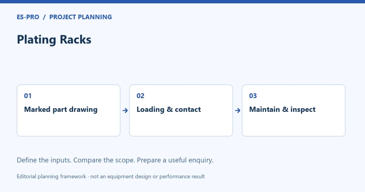
ES-PRO · EQUIPMENT PLANNINGPlating Racks01Marked part drawing→02Loading & contact→03Maintain & inspectEditorial enquiry framework · not an equipment design or performance resultMarked part drawing → Loading & contact → Maintain & inspect. Source: ES-PRO editorial planning framework. Conceptual inputs; not a construction drawing or measured result.
This guide concerns the inputs for tooling assessment and upkeep after rack handling has been shortlisted. For the earlier handling decision, use barrel versus rack plating. The next task is defining how the actual components will be supported, contacted, processed and unloaded.
Where may a plating rack contact the part?
Mark acceptable contact locations, appearance-sensitive surfaces and areas that must remain unmarked or uncoated. State whether the acceptable mark is defined by a drawing, a reference sample or a written inspection criterion.
Give the tooling supplier the part material, coating route and relevant finished dimensions. Include restrictions on deflection, clamping or handling. The proposed contact arrangement should be assessed against those requirements rather than selected solely for convenient loading.
The Nickel Institute Nickel Plating Handbook provides technical background on industrial nickel plating. A project-specific rack assessment still needs the actual parts and process requirement; a general handbook does not validate a proposed fixture.
How should part orientation on a plating rack be assessed?
Use the drawing to identify recesses, pockets, holes and surfaces that require attention during loading, immersion and drainage. Ask the process and tooling specialists to explain the proposed orientation through the approved route.
Consider the entire handling sequence, including loading access, transfer, rinsing, draining and unloading. A part arrangement that is easy to load may create a different problem later in the route. Record the questions requiring a sample assessment instead of treating an initial sketch as an approved design.
For a mixed product range, provide a family schedule. Show which parts use dedicated tooling and which are candidates for shared tooling. Ask how changes will be identified and controlled at the loading station.
What is the usable production load for a plating rack?
State the part quantity, loaded weight and relevant plated-area information for the intended load. Include the carrier or rack itself where the handling assessment requires it. The process owner should approve the load's electrical and process requirements.
Ask how the proposed rack fits within the usable tank space and transfer clearances. Confirm loading and unloading work as well as the processing interval. Do not multiply the theoretical maximum part count by an unexplained cycle rate to claim production capacity.
Our machine selection guide puts load assumptions alongside handling and automation. For tooling, those assumptions need to refer to the exact arrangement proposed for the part family.
A plating rack assessment brief
Input
What to supply or agree
Part identity
Material, drawing revision, dimensions and representative samples
Coating
Approved process route, required surfaces and acceptance requirements
Contact
Permitted positions, mark criteria and loading restrictions
Orientation
Proposed position and features needing immersion or drainage assessment
Load
Part quantity, loaded weight and process-load information
Handling interfaces
Carrier connection, usable tank envelope and transfer constraints
Upkeep
Inspection, cleaning or stripping responsibility and replacement criteria
This is an ES-PRO editorial enquiry framework. It is not a rack construction drawing, current-carrying rating or approval of a loading arrangement.
How should plating rack condition be controlled in production?
Agree inspection criteria with the tooling and process specialists. The routine may need to address contact condition, mechanical damage, insulation condition and fit to the intended part. Identify who checks the rack before loading and how a failed rack is kept out of service.
Specify the approved cleaning or stripping procedure and who performs it. Do not assume that any deposit-removal method is suitable for the rack's construction. Ask the supplier for the relevant operating and maintenance instructions.
Keep tooling identity with the production record where the plant needs to investigate recurring defects. A change in rack condition or contact arrangement should be visible when comparing inspection results across loads. That record can support diagnosis without proving that every defect originates in the rack.
What should a plating rack loading trial demonstrate?
Agree representative parts and the intended load. Demonstrate operator access, retention through the planned handling sequence and the approved processing arrangement. The test method must be agreed with the responsible engineering team before carrying out any abnormal or failure scenario.
Evaluate the finished parts against the specified contact-mark, coating and dimensional requirements. Record the actual rack identity and arrangement used in the trial. If loading changes afterwards, identify the assessment needed before treating the earlier result as applicable.
For a new line, include tooling quantities, spare arrangements, maintenance provisions and loading stations in the supply boundary. The line quotation guide helps ensure these items are assigned rather than left between the tooling and line suppliers.
Questions You May Have:
Can the supplier design a rack from a photograph alone?
A photograph can start the discussion. A confirmed design needs dimensions, material, coating requirements and acceptable contact locations, together with any required sample assessment.
Is the largest possible rack load always the most productive?
No. Compare accepted output using the actual loading work, process requirements and inspection result. The largest theoretical load does not automatically provide the best usable production arrangement.
Can several part families share a rack?
They may be able to after checking contact, retention, orientation and process requirements. Identify each approved arrangement so shared tooling does not create an uncontrolled loading change.
Should maintenance be included in the purchase discussion?
Yes. Ask for inspection, cleaning, stripping and replacement requirements, then identify responsibility for the necessary equipment and records.
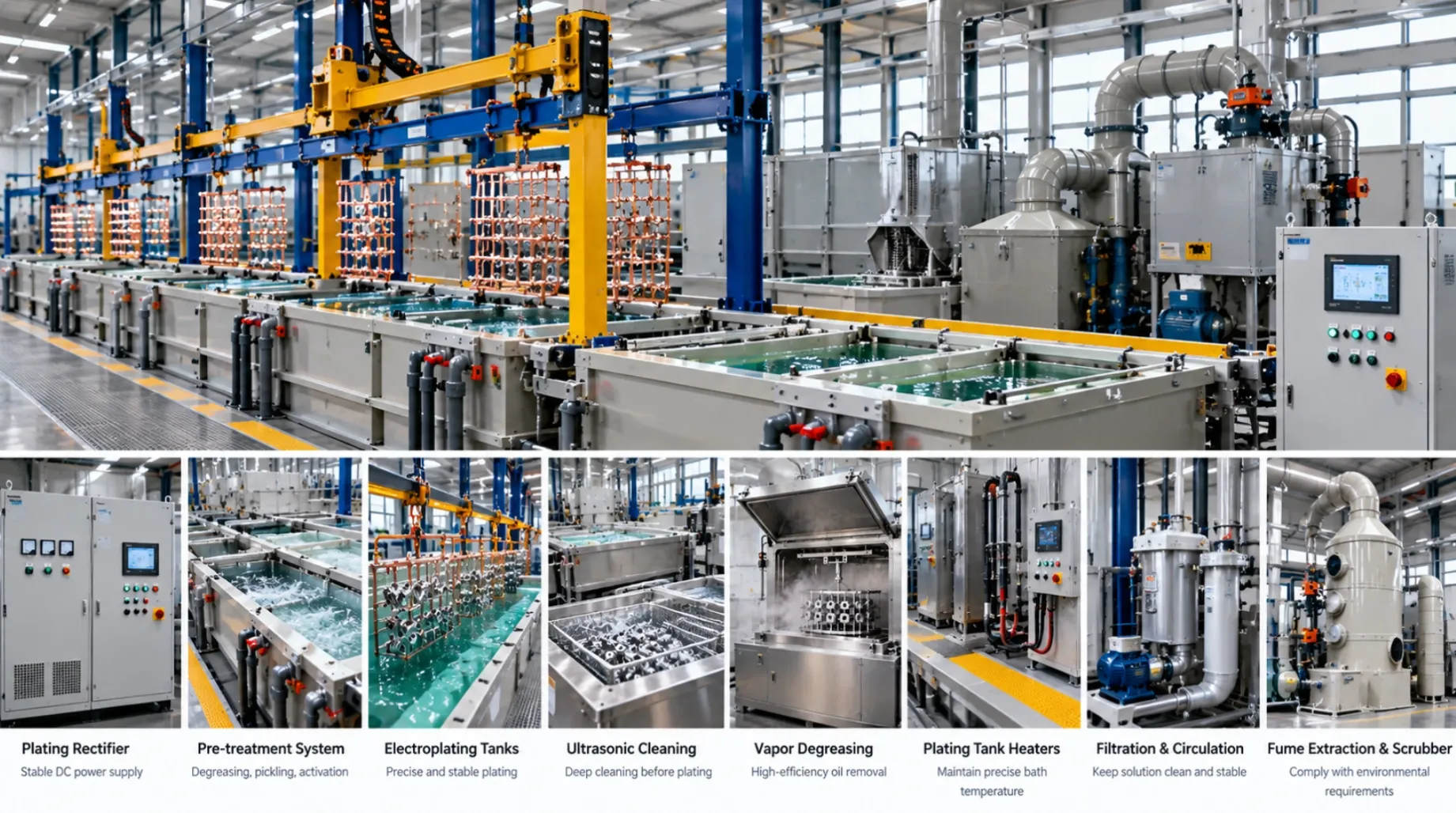
Image note: AI-generated cover illustration; not an ES-PRO installation, customer project or test result.
Plating racks should be assessed against part orientation, electrical contact, acceptable marks, loaded weight and drainage. Begin with a marked part drawing and representative loading requirements. Rack capacity expressed only as a part count leaves important quality and handling questions unanswered, especially when different part families share the same line.
Marked part drawing → Loading & contact → Maintain & inspect. Source: ES-PRO editorial planning framework. Conceptual inputs; not a construction drawing or measured result.
This guide concerns the inputs for tooling assessment and upkeep after rack handling has been shortlisted. For the earlier handling decision, use barrel versus rack plating. The next task is defining how the actual components will be supported, contacted, processed and unloaded.
Where may the rack contact the part?
Mark acceptable contact locations, appearance-sensitive surfaces and areas that must remain unmarked or uncoated. State whether the acceptable mark is defined by a drawing, a reference sample or a written inspection criterion.
Give the tooling supplier the part material, coating route and relevant finished dimensions. Include restrictions on deflection, clamping or handling. The proposed contact arrangement should be assessed against those requirements rather than selected solely for convenient loading.
The Nickel Institute Nickel Plating Handbook provides technical background on industrial nickel plating. A project-specific rack assessment still needs the actual parts and process requirement; a general handbook does not validate a proposed fixture.
How should orientation be assessed?
Use the drawing to identify recesses, pockets, holes and surfaces that require attention during loading, immersion and drainage. Ask the process and tooling specialists to explain the proposed orientation through the approved route.
Consider the entire handling sequence, including loading access, transfer, rinsing, draining and unloading. A part arrangement that is easy to load may create a different problem later in the route. Record the questions requiring a sample assessment instead of treating an initial sketch as an approved design.
For a mixed product range, provide a family schedule. Show which parts use dedicated tooling and which are candidates for shared tooling. Ask how changes will be identified and controlled at the loading station.
What is the usable load for this rack?
State the part quantity, loaded weight and relevant plated-area information for the intended load. Include the carrier or rack itself where the handling assessment requires it. The process owner should approve the load's electrical and process requirements.
Ask how the proposed rack fits within the usable tank space and transfer clearances. Confirm loading and unloading work as well as the processing interval. Do not multiply the theoretical maximum part count by an unexplained cycle rate to claim production capacity.
Our machine selection guide puts load assumptions alongside handling and automation. For tooling, those assumptions need to refer to the exact arrangement proposed for the part family.
A rack assessment brief
Input
What to supply or agree
Part identity
Material, drawing revision, dimensions and representative samples
Coating
Approved process route, required surfaces and acceptance requirements
Contact
Permitted positions, mark criteria and loading restrictions
Orientation
Proposed position and features needing immersion or drainage assessment
Load
Part quantity, loaded weight and process-load information
Handling interfaces
Carrier connection, usable tank envelope and transfer constraints
Upkeep
Inspection, cleaning or stripping responsibility and replacement criteria
This is an ES-PRO editorial enquiry framework. It is not a rack construction drawing, current-carrying rating or approval of a loading arrangement.
How should rack condition be controlled in production?
Agree inspection criteria with the tooling and process specialists. The routine may need to address contact condition, mechanical damage, insulation condition and fit to the intended part. Identify who checks the rack before loading and how a failed rack is kept out of service.
Specify the approved cleaning or stripping procedure and who performs it. Do not assume that any deposit-removal method is suitable for the rack's construction. Ask the supplier for the relevant operating and maintenance instructions.
Keep tooling identity with the production record where the plant needs to investigate recurring defects. A change in rack condition or contact arrangement should be visible when comparing inspection results across loads. That record can support diagnosis without proving that every defect originates in the rack.
What should the loading trial demonstrate?
Agree representative parts and the intended load. Demonstrate operator access, retention through the planned handling sequence and the approved processing arrangement. The test method must be agreed with the responsible engineering team before carrying out any abnormal or failure scenario.
Evaluate the finished parts against the specified contact-mark, coating and dimensional requirements. Record the actual rack identity and arrangement used in the trial. If loading changes afterwards, identify the assessment needed before treating the earlier result as applicable.
For a new line, include tooling quantities, spare arrangements, maintenance provisions and loading stations in the supply boundary. The line quotation guide helps ensure these items are assigned rather than left between the tooling and line suppliers.
Questions You May Have:
Can the supplier design a rack from a photograph alone?
A photograph can start the discussion. A confirmed design needs dimensions, material, coating requirements and acceptable contact locations, together with any required sample assessment.
Is the largest possible rack load always the most productive?
No. Compare accepted output using the actual loading work, process requirements and inspection result. The largest theoretical load does not automatically provide the best usable production arrangement.
Can several part families share a rack?
They may be able to after checking contact, retention, orientation and process requirements. Identify each approved arrangement so shared tooling does not create an uncontrolled loading change.
Should maintenance be included in the purchase discussion?
Yes. Ask for inspection, cleaning, stripping and replacement requirements, then identify responsibility for the necessary equipment and records.
Specify automated metal finishing with clear operator tasks, recipe control, load records and recovery rules. Compare automation scope before ordering a line.
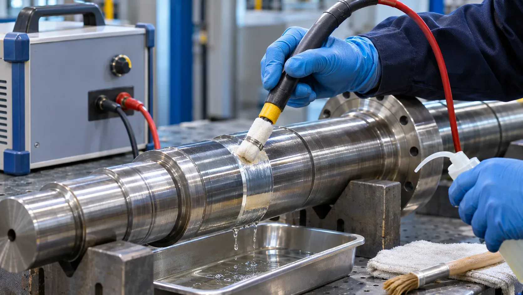
Selective plating (also called brush plating or swab plating) is the electroplating equivalent of a precision tool — it deposits metal on a defined area of a part without immersing the whole component
Tell us about your workpiece, coating process and production target. We can review the handling format and equipment scope before discussing a line configuration.
Email
sales@electroplating-equipment.com
Project inquiry
Get Proposal and Demo
Company name, your name, email and project country are required. Phone, city and technical details are optional. Submit without files; send drawings or technical documents to sales@electroplating-equipment.com.