Applications
Gold Contact Plating Thickness and Coverage Maps
Map gold thickness and coverage on contact parts before requesting a quote. Define critical zones, measurement locations and the deposited-volume basis.
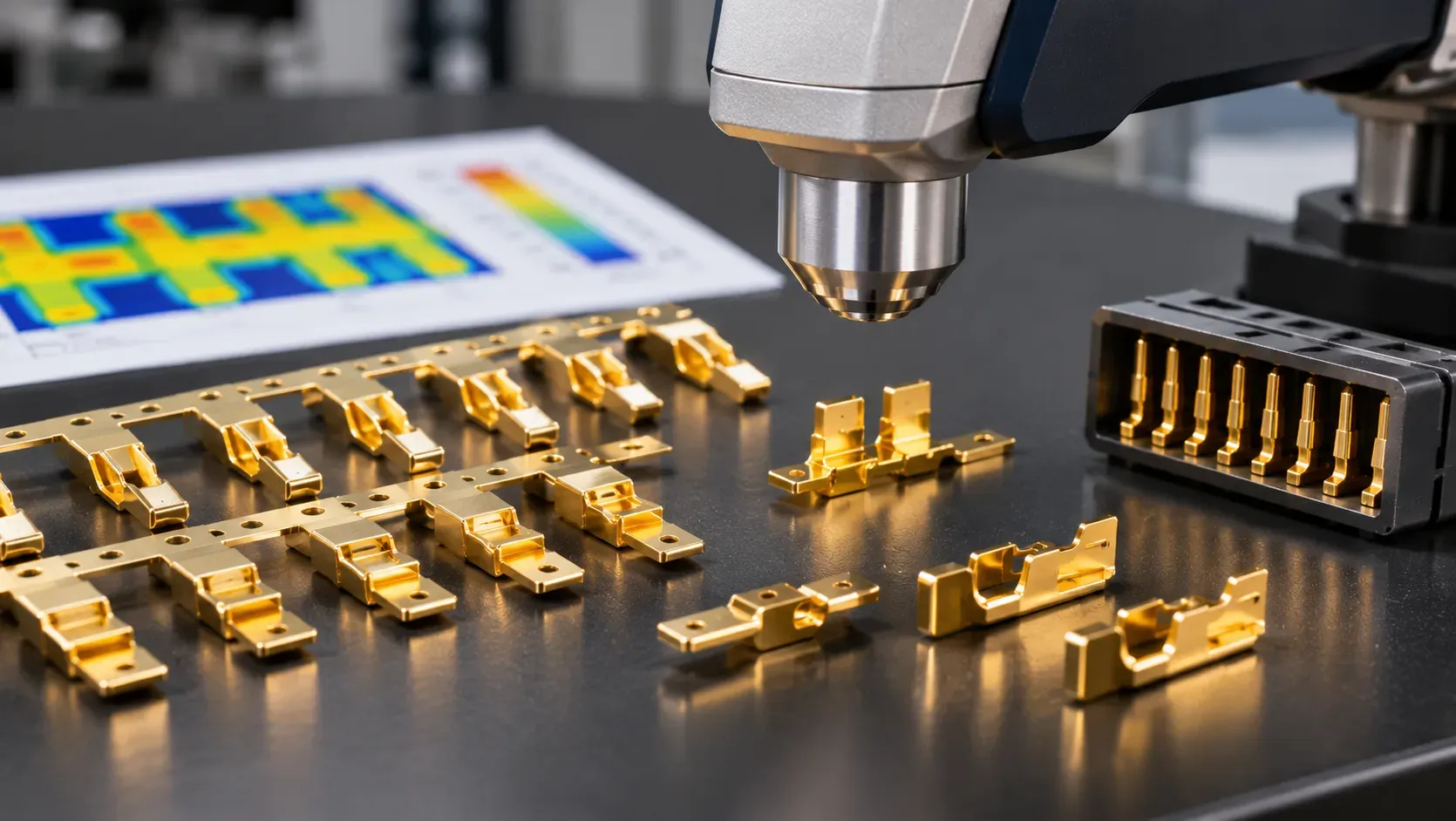
Specify gold contact plating with a marked coverage region, the required coating system and named measurement locations. Connect thickness to the function and final acceptance criteria for that region. Use the map to estimate deposited volume and define selective-processing and inspection duties, then qualify the result on representative contact parts.
A note saying “gold flash” or a single thickness value can leave the required area and coating type unclear. The buyer needs a complete callout so suppliers can quote the same contact region and evidence.
Separate coverage from inspection locations
Mark the area that needs gold, any transition allowance and surfaces excluded from coating. Identify the substrate, underlayers and required gold classification from the controlling specification. Mark where thickness and other required properties are checked.
The ASTM B488 public scope addresses electrodeposited gold coatings for engineering uses and distinguishes its coverage from other deposition methods. Use the project-invoked document and drawing to establish purity, hardness, thickness and acceptance.
Map item | What to record | Quotation consequence |
|---|---|---|
Functional contact region | Drawing zone and coverage tolerance | Required plated area |
Coating system | Underlayers and complete callout | Stage sequence and process requirements |
Inspection points | Feature, method and required evidence | Measurement access and sampling plan |
Transition or exclusion | Permitted boundary and protected features | Selective tooling or masking |
Work through a deposited-volume example
Suppose 1,000 hypothetical contacts each require gold over 0.4 square centimetres at an illustrative thickness of 1 micrometer. The total coated area is 400 square centimetres. One micrometer is 0.0001 centimetres, giving a calculated deposited volume of 0.04 cubic centimetres.
If the selected coverage grows to 0.6 square centimetres per contact at the same thickness, the calculated volume becomes 0.06 cubic centimetres. That is a 50 percent increase in the idealized deposited volume. These are calculation inputs, not a recommended finish thickness or a chemical consumption prediction.
Actual process consumption and cost need the supplier's production basis. The approved deposit distribution, processing losses and other operating duties are separate from this ideal geometric calculation. Keep them separate in the quotation so a coverage change can be evaluated transparently.
Have a second reviewer confirm the unit conversion and selected CAD surfaces before the estimate enters the bid comparison.
Qualify the boundary and the critical feature
Use representative parts and the intended load or feed arrangement. Inspect the coverage boundary and the required thickness locations using the approved method. Record how any selective tooling or mask is positioned and checked.
If an area is difficult to measure, resolve the inspection basis before trial approval. The coating thickness testing guide helps discuss access and method. A convenient reading outside the functional region should not silently replace the drawing's required location.
Keep the contact's final condition and service test connected to the coating evidence. An acceptable boundary and thickness map support their defined requirements. The assembly's electrical or mechanical acceptance still follows the project plan.
Turn the map into a comparable bid
Give each supplier the same drawing revision, coverage map, coating callout and accepted output basis. Ask which tooling, inspection and maintenance tasks are included. If the process uses continuous feed, identify how the functional region stays aligned with the selective operation.
The electronics gold-plating guide provides application context. The selective plating guide helps compare local-coverage approaches.
Record part revision · gold region and tolerance · coated area method · complete system · thickness locations · selective-tool revision · trial results · volume calculation · open items and owner. Recalculate the estimate when a drawing or coverage boundary changes.
Review a proposed coverage change before releasing it
Overlay the revised region on the accepted drawing and mark the surfaces added or removed. Recalculate the ideal area and volume, then review tooling alignment, boundary inspection and any affected assembly contact. A smaller plated region can save geometric deposit volume while creating a tighter positioning requirement.
For a trial, include the part and feed conditions that exercise the proposed boundary. Record how the tooling locates the part and which variations the test represents. If a drawing tolerance allows the functional contact to approach the transition zone, have the quality and design teams specify the acceptance check there.
Ask the bidder to show which costs and equipment duties actually change with the revised map. Distinguish deposited-area assumptions from tool maintenance, measurement and handling so the commercial comparison remains traceable.
Procurement checklist
- The drawing revision, gold coating designation and separate coverage and measurement maps.
- The per-part area basis, units, planned quantity and any qualified coverage boundary allowance.
- A priced split for selective tooling, inspection, recovery and metal-accounting responsibilities; identify assumptions behind consumption estimates.
FAQ
Is “gold flash” a complete engineering callout?
Ask for the controlling coating designation, required area, thickness and acceptance criteria.
Can geometric deposited volume predict bath purchases?
Use it as an area-and-thickness calculation. Obtain the actual consumption basis from the approved process and supplier.
Should inspection include the selective boundary?
Include it when coverage limits, transition zones or excluded surfaces are controlled by the drawing.
Discuss a selective gold-plating brief
Share the contact and coverage map. Include the coating callout, measurement points and planned output. Send drawings by sales email, or discuss the project on WhatsApp.